The Engineering Behind Every TitanWatt Power Stage
Four disciplines carry each CRPS and M-CRPS platform from specification to shipment: efficiency topology, thermal management, digital telemetry and reliability verification. The same 96%-peak-efficiency target, 250,000-hour MTBF discipline and PMBus 1.2 command set that appear on our datasheets are engineered and verified in-house — on our own SMT+DIP lines, automated test equipment and burn-in rooms. This hub goes one level deeper than the homepage: what each capability actually covers, and how it maps to the wattage segments you can order today.
Four Capability Pillars
Titanium Efficiency Engineering
LLC resonant conversion with synchronous rectification, paired with a DC-PFC front end, holds 96% efficiency at 50% load on the 230V redundant curve — the 80 PLUS Titanium gate of 90/96/91% across the 10/50/100% load points.
Standby draw is held under 0.5W with +5VSB active, and power factor stays at or above 0.95 at half load, so a 10kW rack slot wastes roughly 430W less per hour than a Gold-class equivalent.
Explore efficiency engineering →Thermal Design & Derating
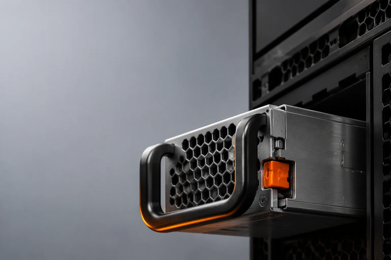
A twin 40mm fan array, NTC sensors on the primary bridge, transformer and output rectifiers, and selectable front-to-back or back-to-front airflow keep full output from -5°C to +55°C ambient with no hidden derating cliff in the chart.
High-conductivity potting and soldered heatsink joints move heat off the switch nodes, which is what allows the 73.5×40×185mm CRPS-185 envelope to hold up to 2400W in production today.
Explore thermal design →PMBus Telemetry & Control
Every intelligent unit speaks PMBus 1.2 over I²C, exposing input/output voltage and current, temperatures, fan speed and fault status — plus fleet commands for power throttling, cold redundancy sequencing and active current sharing.
Output-voltage setpoints, warning thresholds and fan curves can be customized per project, and a graphical monitoring tool mirrors the same registers for remote rack-level supervision.
Explore PMBus telemetry →Testing & Reliability
The reliability chain runs ATE electrical test, then extended burn-in in dedicated aging rooms, then the safety lab — with Telcordia SR-332 MTBF predictions of 250,000 hours or more at 40°C backing the design, not just the marketing copy.
Five protection circuits (OVP, UVP, OCP, OTP, fan-fail) are verified at every gate, and certification to IEC/UL 62368-1 with CB, CE, UKCA, FCC, RoHS and REACH coverage is maintained on the production platform.
Explore testing & reliability →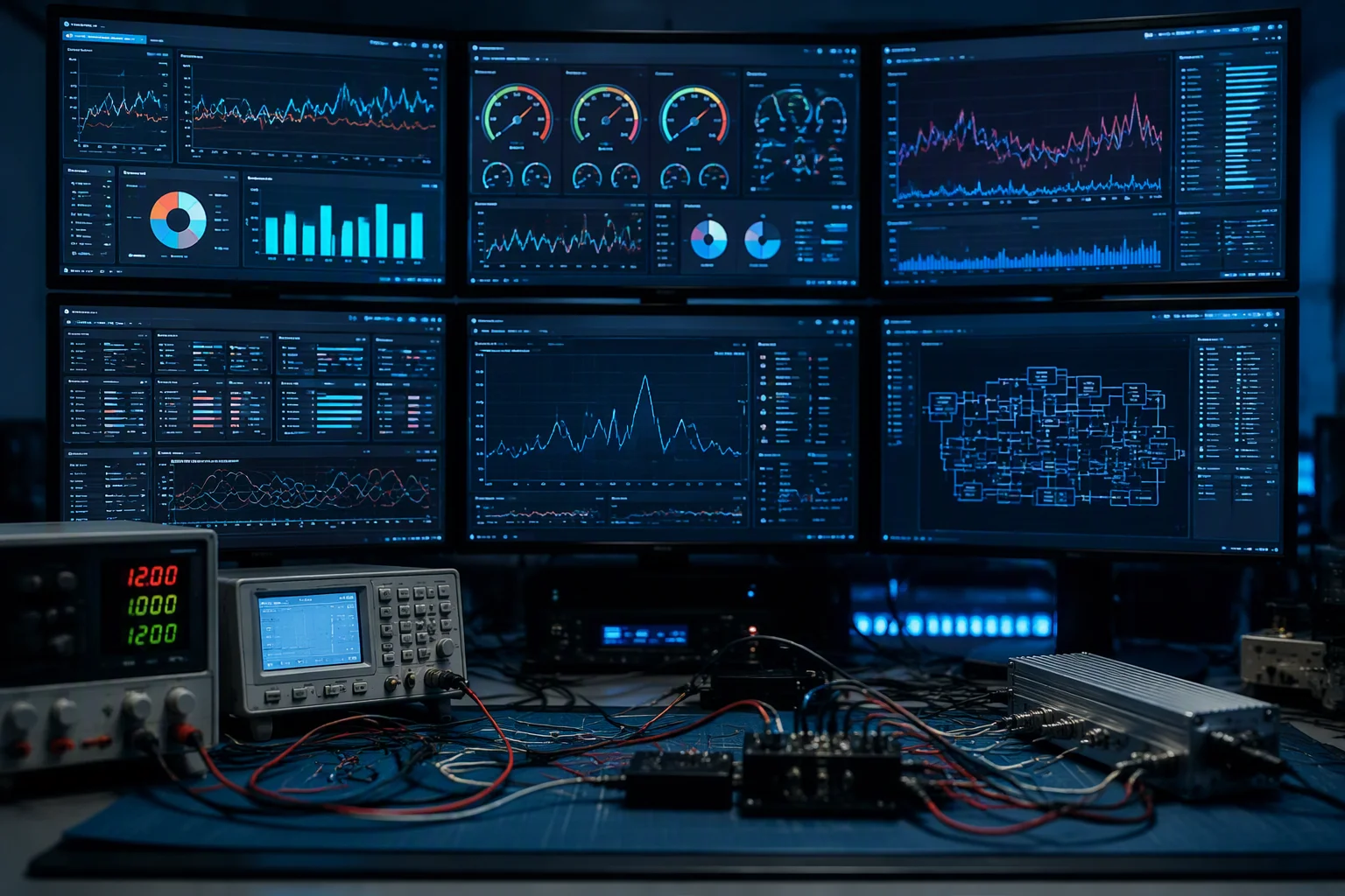
Digital Power, Visible End to End
PMBus telemetry is designed in with the control firmware, not bolted on after layout — which is why the same command set scales from a 550W enterprise unit to a 5.5kW M-CRPS development sample.
Verified on Our Own Floor
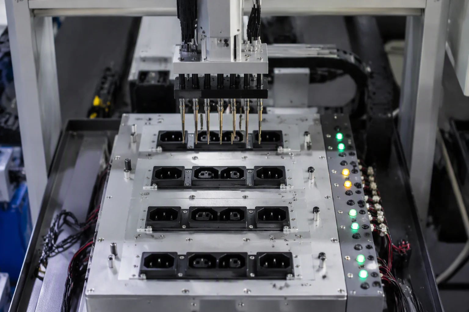
SMT+DIP assembly, automated test equipment and burn-in rooms sit under one roof, so reliability data comes from the same line that builds your volume — no third-party test shortcut.
Which Segments Each Capability Covers Today
Engineering effort is not spread evenly across the roadmap. Here is where each discipline is proven in production versus where it is being extended.
| Wattage segment | Status | Capability emphasis |
|---|---|---|
| 550W – 1300W CRPS | In production | Full titanium curve, dual airflow options, complete PMBus command set |
| 1600W – 2400W CRPS | In production | 75 W/in³-class density thermal stack, active current sharing, C19 input |
| 3000W – 5500W M-CRPS | Development Samples | 54V output architecture, ORv3 slot compatibility as target specification |
| 8kW / 12kW / 33kW shelf | Roadmap | Joint-development phase: busbar distribution, shelf-level telemetry |
How a Platform Moves Through Our Floor
Every production and development unit passes the same six gates. The gates are fixed; the depth of testing at each one scales with the wattage class and your specification.
Joint review of rail budgets, airflow direction, PMBus command set and target certifications against the CRPS-185 or M-CRPS envelope.
Topology selection (LLC + DC-PFC), thermal simulation of the 40mm fan path, and loss budgeting against the 96% @ 50% load target.
Engineering validation units on the SMT+DIP line, with full ATE sweep across 10%, 50% and 100% load points at line and low line voltage.
Design validation with burn-in aging, protection-circuit trip verification (OVP/UVP/OCP/OTP/fan-fail) and MTBF prediction review.
Mass production under ISO 9001 process control, with safety-lab verification per build lot and full serial traceability.
Every shipment leaves the burn-in room with per-serial test records; samples ship in 2–4 weeks and volume in 6–10 weeks.

Bring Your Power Specification to Our Engineers
Send your rail budget, airflow and telemetry requirements — we reply within 48 hours with a capability match and a platform recommendation.