Design Guides for Server Power Engineering
Five working references from the TitanWatt engineering floor: how to budget power honestly, how to confirm a CRPS module will physically and electrically drop into your chassis, how to bring PMBus telemetry into your BMC, what actually changes when you move from 12V to a 54V bus, and how to design the airflow around a 2400W module. Each guide is written to be used with a datasheet open — no marketing, just the arithmetic and the checklists.
CRPS Selection: the Power Budget, Worked Out
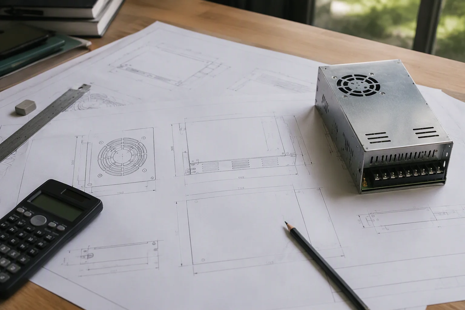
Start from component nameplate numbers, then correct them — nameplates are worst-case, not typical. A 2U enterprise node is a fair example: CPU at a 205W TDP, eight 28W DIMMs, six NVMe drives at 12W typical each, chipset and board logic around 40W, and two 25W fans with headroom. The DC budget reads: 205 + (8×28) + (6×12) + 40 + (2×25) = 537W typical. Apply a 20% transient and aging margin and allow for peak CPU bursts above TDP, and the honest requirement lands around 650W.
That number drives the redundancy decision: one 800W unit gives N only; two 550W units in N+1 give you redundancy and keep each module at roughly half load in normal operation — which is exactly where an 80 PLUS Titanium unit sits at its 96% peak efficiency point. Staying near 50% load also keeps fan acoustics and capacitor stress down. The rule of thumb: pick the wattage that lets redundant modules run near half load, not the wattage that barely covers nameplate sum.
See the 550W–1300W platforms →Chassis Compatibility Checklist
"CRPS-compatible" hides a dozen details. Run this list before ordering samples:
Mechanical
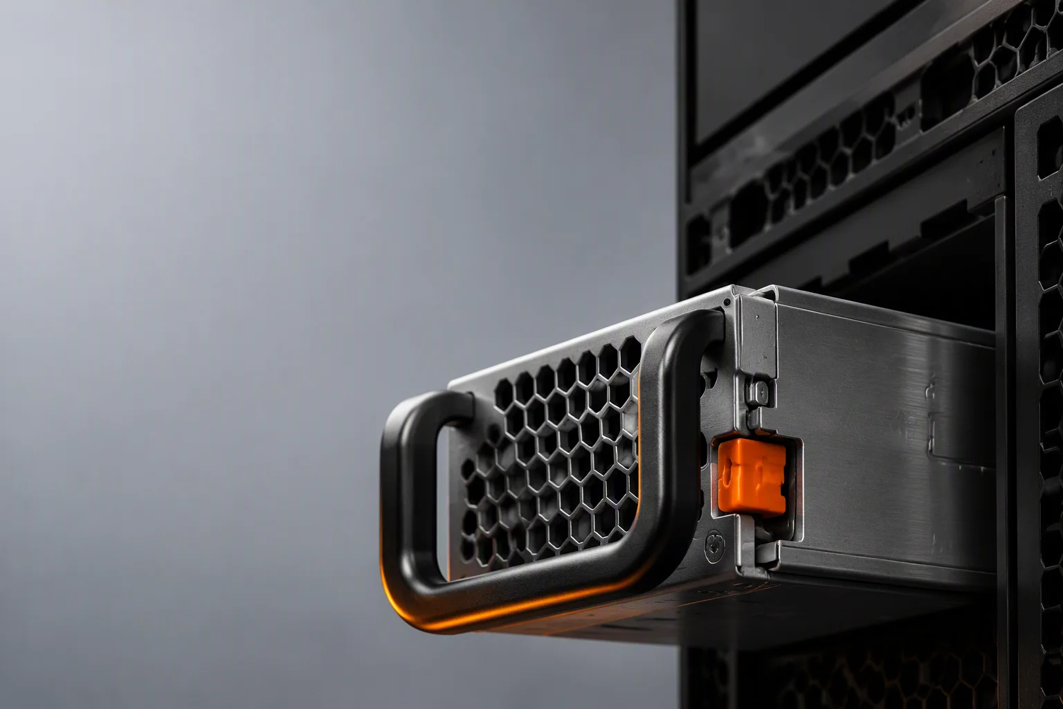
Confirm the envelope: standard CRPS1 is 73.5×40×185mm in 1U height. Check handle clearance and the release-latch direction in your cage, the extraction path against cable routing, and whether your chassis expects the fan face front-to-back or back-to-front — airflow direction is selectable on TitanWatt units, but it must match the rack's thermal plan.
Electrical interface
Verify the golden-finger pinout against your motherboard: 12V rail grouping, +5VSB standby, PS-ON, PS-KILL, POK/PWR-OK polarity, and the I²C/PMBus pins. A mismatched POK polarity is the classic silent failure — the system boots on the bench and blocks POST in the rack.
Input & environment
Check the inlet: C14 for lower-wattage units, C20 for 1600W+ class. Confirm your region's nominal input (100–127V vs 200–240V) — efficiency curves are specified on the 230V redundant line, and low-input operation derates output. Confirm the -5°C to +55°C ambient spec covers your worst rack zone, not just your average one.
Telemetry & firmware
Probe PMBus 1.2 registers from your BMC before mass deployment: read VOUT/IOUT/TEMP/FAN, test the warning-threshold writes, and confirm your firmware matches the unit's command map. TitanWatt provides a register map and validation procedure with every sample kit.
PMBus 1.2 Integration With Your BMC
Plan the integration in three passes. First, monitoring: poll input/output voltage, output current, both temperature zones and fan speed — the four registers that give you a health trend line. Poll at 10–30 second intervals; faster buys you nothing and floods the bus with a 20-module shelf. Second, thresholds: configure warn/fault limits so your BMC logs a degradation event (fan speed creeping up at constant load is the earliest thermal warning you will get) rather than only a trip.
Third, control: PMBus 1.2 gives you PS-KILL, PS-ON, power-throttling coordination and faultClear. In N+1 arrays, use telemetry to rotate which module carries the load-share lead, equalizing wear; in cold-redundancy schemes, keep spare modules dark until telemetry from the active ones says otherwise. Validate every command on one unit before scripting it across the fleet — the TitanWatt GUI monitor tool mirrors the same register map, so an operator can verify behavior without writing firmware.
Deep dive: PMBus telemetry →Migrating to a 54V Bus: What Actually Changes
The physics is simple: at 54V instead of 12V, the same power flows at one-quarter the current, and resistive line losses — I²R — drop by roughly 16×. In a 40–120kW AI rack, where busbar runs run tens of centimeters between shelf and GPU tray, that difference is the line between copper you can route and copper you cannot cool. This is why the ORv3 ecosystem standardized on 54V, and why a 33kW shelf is built from six 5.5kW modules in a 5+1 array.
What changes on your side: GPU boards need on-board 54V-to-load converters (step-down ratio rises, so plan for multi-stage conversion on the tray); safety creepage and clearance rules move because the distribution bus is now hazard-level voltage; and your battery/backup strategy must be 48V-native or converted. What does not change: AC input, hot-swap mechanics, and PMBus telemetry all remain CRPS-style, which is why the M-CRPS platform keeps the familiar 73.5×40×185mm envelope with a modular output section. Our 3.3kW/5.5kW M-CRPS units are in the development-samples stage for exactly this migration path — evaluate them against your tray design now, not after the busbar is cut.
See the M-CRPS development program →Thermal Design Checklist for Power Bays
Decide front-to-back or back-to-front for the whole chassis, then order PSU airflow direction to match. A counter-flow power supply recirculates hot air through the server — a common cause of "mystery" thermal throttling in mixed-vendor racks.
Spec is continuous full output from -5°C to +55°C ambient — measured at the PSU inlet, after preheating from upstream components. Check the worst-case zone: the last bay in a stack of hot-swap modules sees the hottest air.
Twin 40mm fans move a lot of air through a 40mm-tall module, but only if intake is not choked. Leave the service-clearance zone around the fan face free of cables and blanking-panel leakage, and keep inlet meshes serviced.
During validation, log PMBus fan speed and internal temperatures under full load. If fan RPM climbs week over week at constant load, dust load or a blocked path is eroding your margin — fix the bay, not just the unit.
Verify there is no hidden derating between 40°C and 55°C on the vendor curve. Titanium platforms we build hold specified output across the full -5°C to +55°C window — insist on the same from any supplier.