GPU Server Power Supply Solutions
Accelerators rewrote the power budget of the rack. A single H100 SXM draws 700W, a B200 draws 1000W, and an 8-GPU HGX node crosses 10kW of system load before storage and networking say a word. This page lays out how TitanWatt production parts — titanium CRPS arrays today, 54V M-CRPS in development — combine into power architectures per node type, with the telemetry to see trouble coming.
What GPUs Demand From the Power Chain
| Reference Point | Figure | Power-Chain Consequence |
|---|---|---|
| NVIDIA H100 SXM GPU | 700W per GPU | Board VRMs need stiff 12V/54V feed, low ripple under transient load steps |
| NVIDIA B200 GPU | 1000W per GPU | Per-GPU draw now exceeds one 1300W PSU's comfortable share — arrays mandatory |
| 12VHPWR card connector | 600W ceiling | Card-level cabling margin vanishes; distribution voltage must rise |
| HGX 8-GPU node | 5.6kW–8kW bare GPU, 10kW+ system | 3–5.5kW PSUs × N+1, no single-module failures tolerated |
| AI rack density | 40–120kW per rack | Shelf-level 54V distribution; traditional 5–10kW rack assumptions obsolete |
| Load transients | Sub-millisecond full-throttle steps | Hold-up and sharing control must react faster than host throttling |
| Fleet duty cycle | Near-continuous training load | Efficiency at 50–80% load dominates TCO; titanium 96% @ 50% matters |
Power Topology, Stage by Stage
AC Input
200–240Vac branch circuits land on rack PDU outlets; C19 feeds per PSU. Power factor ≥ 0.95 at 50% load keeps the branch honest.
CRPS Array
3–6 hot-plug titanium modules, 1600W–2400W each today, active current sharing across the bus; N+1 with PMBus health per slot.
54V Busbar
54V (or 12V for legacy nodes) distribution: the same power through a fraction of the current, keeping line loss and connector heating manageable at multi-kilowatt draw.
GPU Boards
On-board VRMs step down to sub-volt rails per GPU. The PSU's job ends at a clean, telemetry-visible feed and fast throttling signals.
Today: stages 1–2 built from in-production 1600W–2400W CRPS titanium. In development: stages 2–3 native at 54V via the M-CRPS 3000W–5500W program.
Solutions by Node Type
1–2U GPU Servers
One to four low-profile accelerators, 1.5–3kW system draw. Two to three 1300W–1600W CRPS units in N+1 at 12V — no intermediate conversion stage, minimum parts count, full PMBus visibility.
HGX-Class Nodes
8-GPU nodes at 10kW+ system load. Four to five 2400W CRPS front-end units with active current sharing, oversubscribed 5×2.4kW = 12kW against a 10kW draw, or N+N cabling across two PDUs for dual-domain fleets.
Full AI Racks
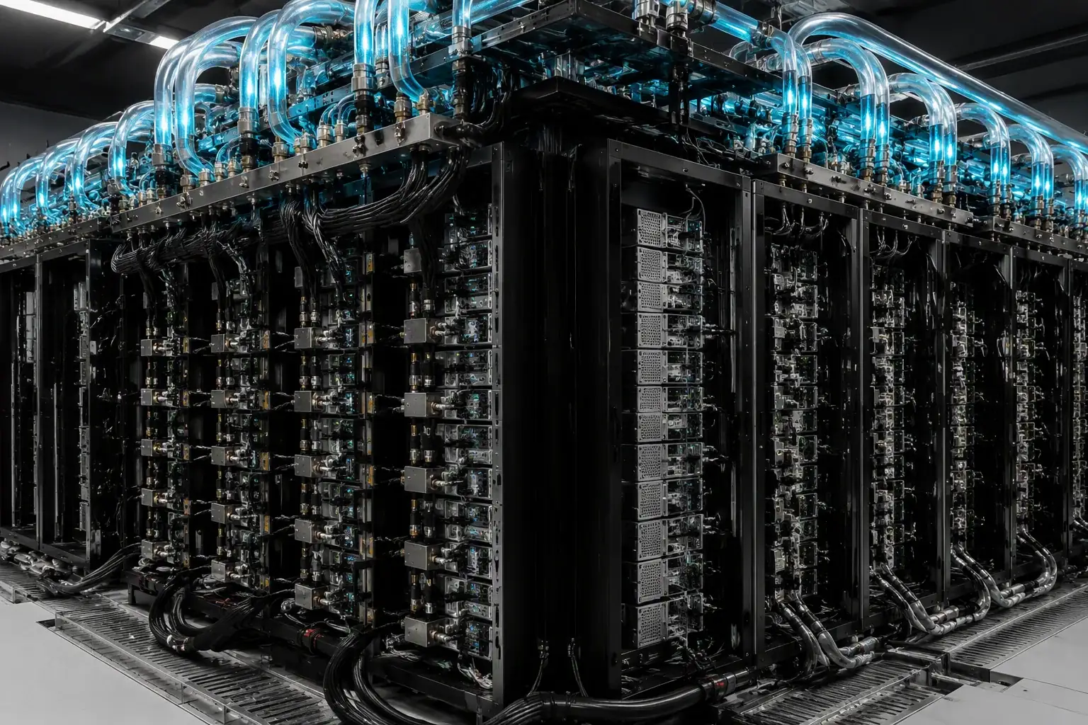
40–120kW racks want shelf-level 54V. Our 5.5kW M-CRPS development samples target the ORv3 slot so the same module serves nodes now and shelves next — one qualification across your roadmap.
See the Failure Before It Costs $9,000
Uptime Institute pegs data center downtime near $9,000 per hour, and in a GPU cluster the power front-end is the single most exposed shared element. Every TitanWatt smart PSU streams voltage, current, temperature and fan RPM over PMBus 1.2, so your BMC can trend capacitor aging and fan bearing wear instead of discovering them mid-training run.
When a module does drop, power throttling lets the host shed load in an ordered sequence, and cold redundancy brings a rested spare online that has already proven itself. The failure becomes a maintenance ticket scheduled between training jobs — not a terminated checkpoint.
PMBus telemetry details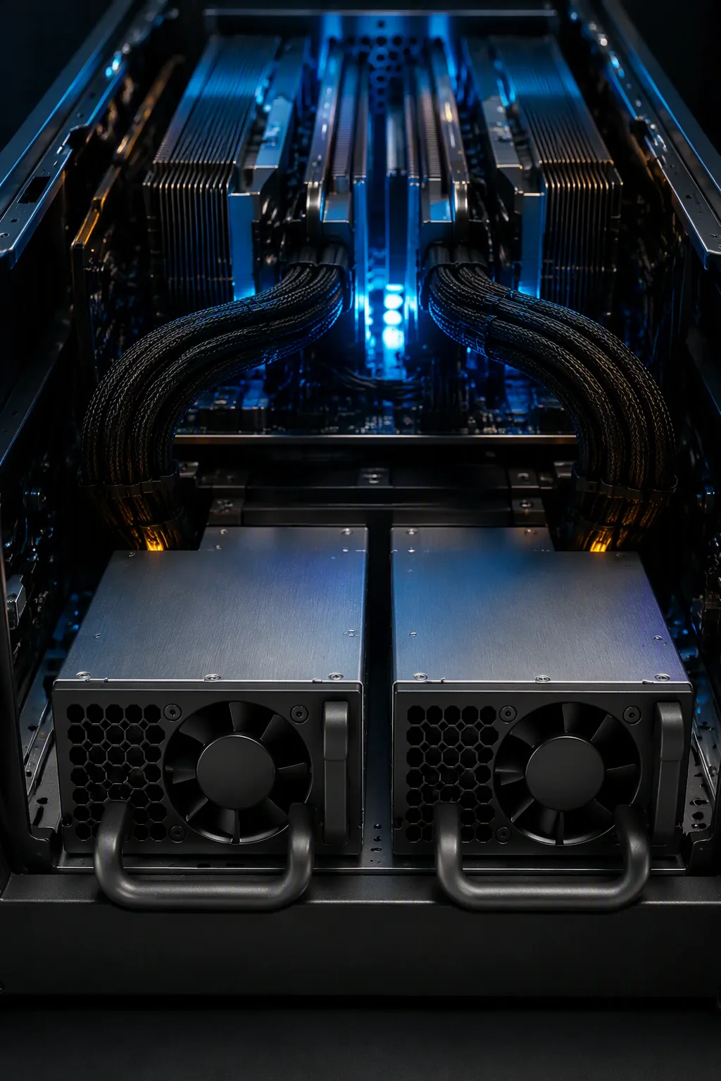
Where the Power Front-End Lives
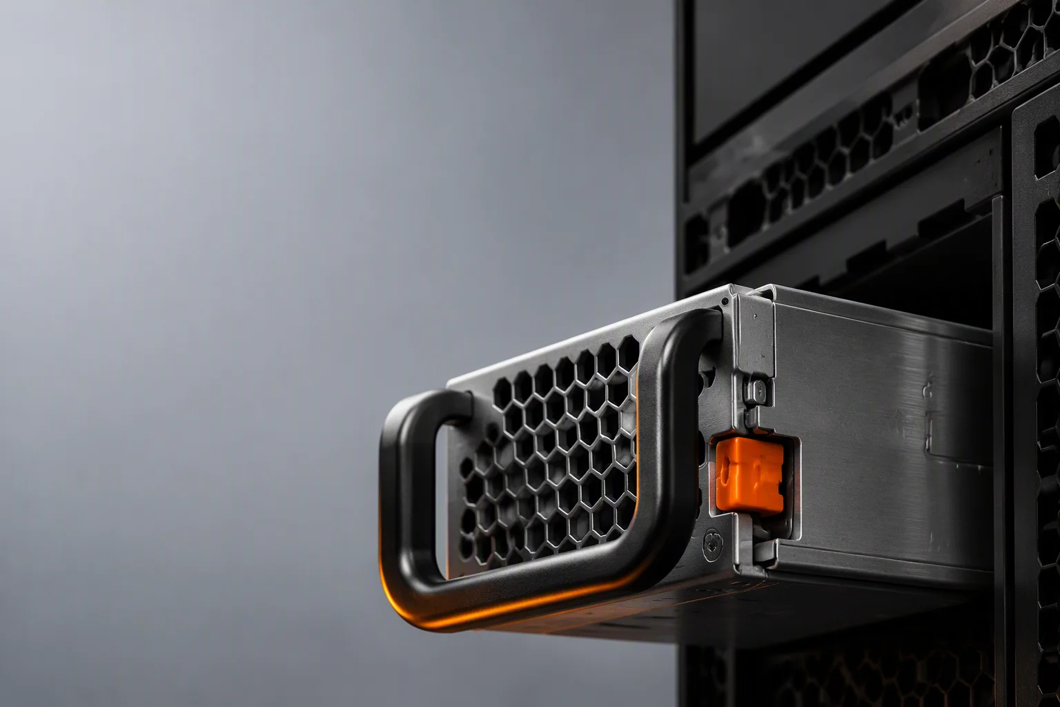
In an 8-GPU node the supplies sit at the very back of the thermal path — last in the airflow, first to be blamed. Handle-out access, front or back airflow options and per-rail telemetry exist so that the most exposed shared component is also the easiest to inspect and replace.
From Our Project Log
AI cluster front-end program: a customer building a training cluster engaged us on the 5.5kW M-CRPS path while standardizing our in-production 2000W CRPS units for their existing 2U nodes — one supplier, both rungs of their ladder, with the 54V transition designed in rather than bolted on. Project details are anonymized in our projects log.
FAQ

Size Your GPU Power Chain
Send your node or rack configuration — we reply within 48 hours with an array sizing and sourcing plan.