Thermal Design & Derating
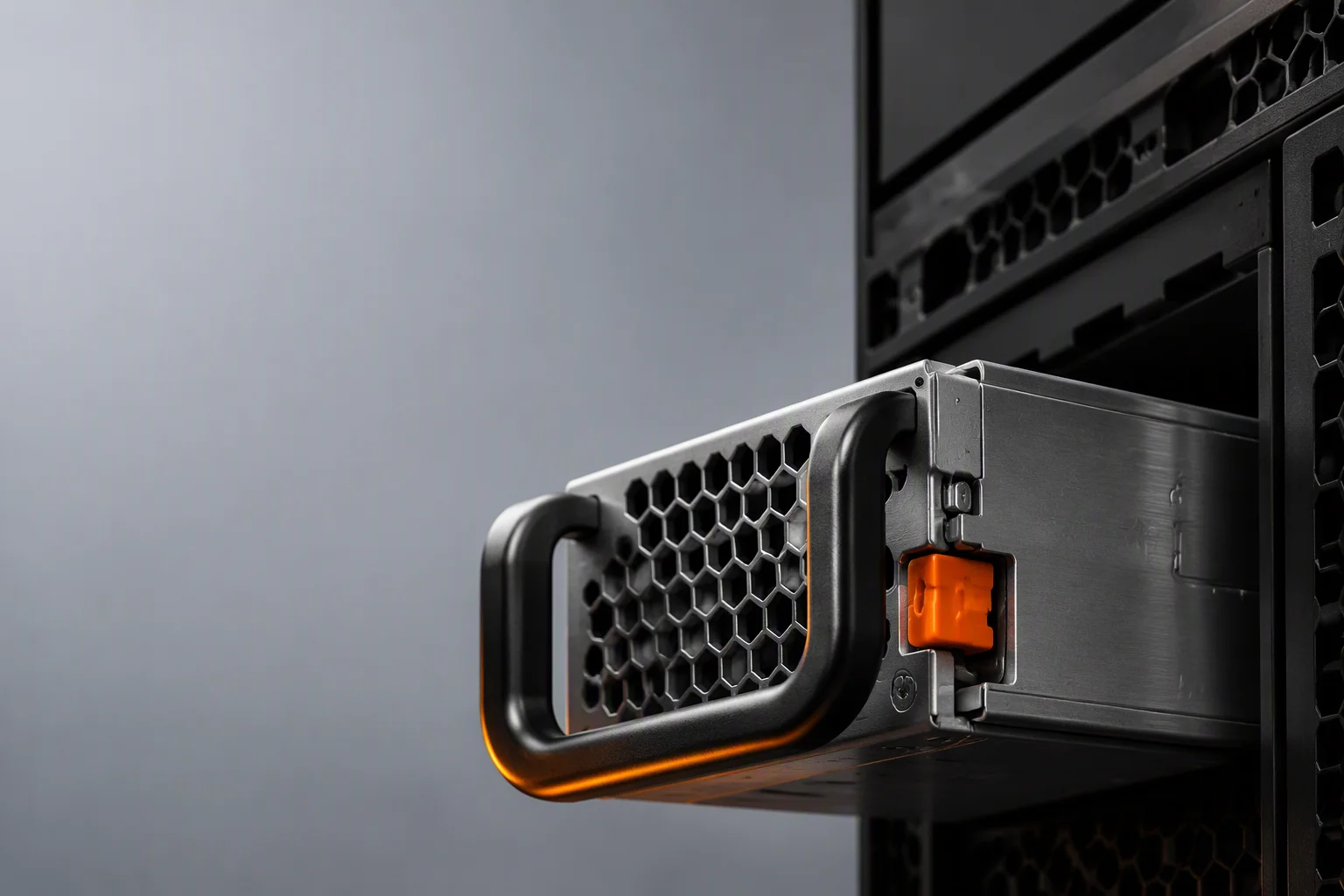
Inside a 73.5×40×185mm CRPS-185 shell there is roughly one liter of volume in which a 2400W production unit must dissipate everything its 96%-efficient conversion does not deliver — about 100W of heat at full load. Thermal engineering is therefore not a chapter of our design reviews; it is the constraint that shapes component placement, fan selection, airflow direction and, ultimately, the -5°C to +55°C full-output operating window we commit to on the datasheet.
The Heat Path, From Junction to Rack Exhaust
Twin 40mm Fan Array
Two 40mm fans in the classic CRPS arrangement provide redundancy in themselves: if one fails, the fan-fail protection circuit raises the survivor's PWM duty and alerts the BMC over PMBus while the unit keeps its derated output.
NTC Placement Where It Counts
Temperature sensors sit on the primary switching bridge, the transformer winding and the output rectifier block — the three hottest nodes — so OTP trips on real junction-proximate readings, not on inlet air guesswork.
Airflow Direction, Your Choice
Front-to-back and back-to-front airflow are build options on the same platform, so a ToR switch with rear exhaust and a storage JBOD with front intake can share one qualified power supply design.
Temperature vs. Output Capability
Our production CRPS platforms hold full rated output across the entire -5°C to +55°C ambient range with no derating cliff — a deliberate design target, because racks rarely cool down at peak compute.
Materials and Process Behind the Window
High-conductivity potting. Critical hot-spot regions are potted with a thermally conductive compound that spreads heat into the chassis walls, cutting local hot spots on dense 1600W–2400W layouts where component-to-component clearance is tightest.
Soldered heatsink joints. Where a bolted heatsink would add interface resistance and a assembly-tolerance variable, we solder the joint — repeatable across every unit on the line and verifiable in cross-section during DVT.
Fan control firmware. The PWM fan curve is tuned per wattage segment and can be customized per project, balancing acoustic limits in office-adjacent deployments against headroom in 40°C+ edge rooms.
Burn-In Screening Closes the Loop
Thermal design is only as good as its verification. Every shipment passes through dedicated burn-in rooms where units run at elevated temperature and load until early-life failures surface — the infant-mortality window that field operation would otherwise discover for you — on someone else's production schedule.
Validated in the Wind Tunnel, Not on Paper
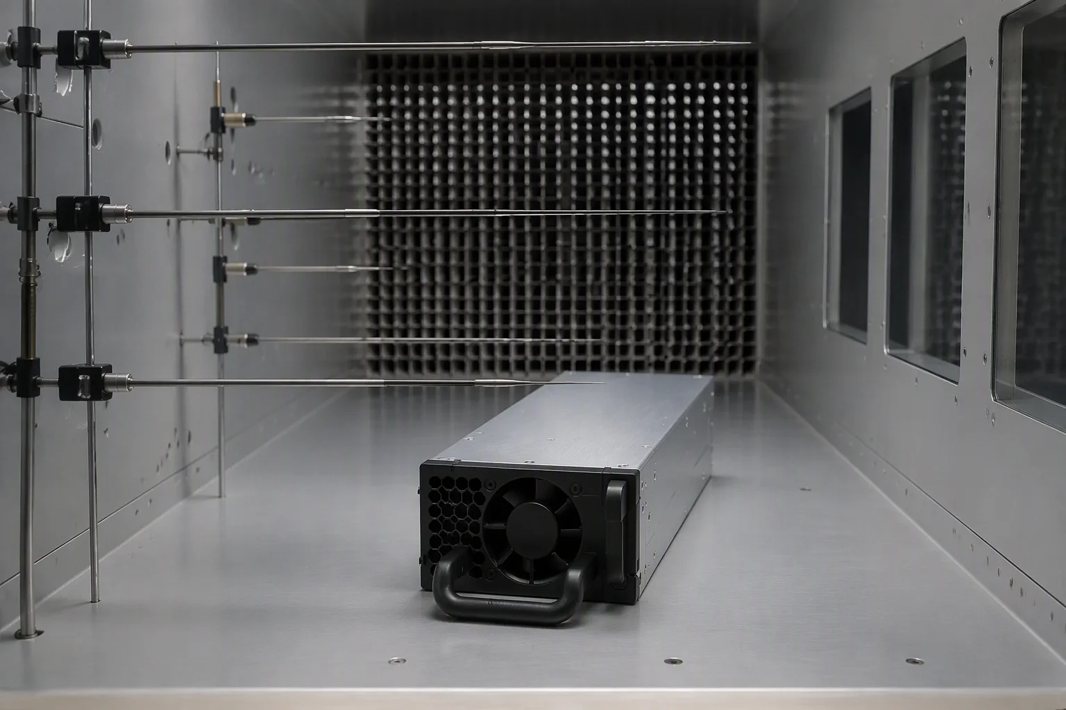
Every thermal design passes through our wind-tunnel section with upstream probes and straighteners before it sees a datasheet. The result: derating curves you can plan a chassis around, and a fan curve matched to real back pressure instead of an idealized one.
Thermal Engineering FAQ

Match Our Thermal Window to Your Rack
Share your chassis airflow, inlet temperature and altitude — we reply within 48 hours with the right airflow option and fan-curve configuration.