Power for ToR & Spine-Leaf Switches
The leaf-spine fabric of every modern fabric — ToR switches at the rack, spine and leaf layers above them — lives or dies by two constraints that keep tightening together: port density and rack space. As switch silicon moved from 100G toward 400G and now 800G ports, the power a 1RU switch must ingest keeps climbing, while the 1RU itself has less and less room for fans and heat. Networking power is a packing problem with electrical consequences.
Three Squeezes on the 1RU Power Budget
Port density drives silicon draw
Every step up the port ladder — 100G to 400G to 800G — adds SerDes lanes and optical power per front panel. A switch chassis that drew a comfortable few hundred watts a generation ago now budgets toward a kilowatt in the same 1RU, which pushes the supply from the 550W shelf straight into the 800W-1300W band and beyond.
Airflow must match the rack, not the datasheet
Data center rows are laid out with a single airflow direction: front-to-back or back-to-front. A switch whose PSU fights the row's direction becomes a recirculation heater for the whole rack. Offering the same electrical unit in both airflow orientations is not a nice-to-have — it decides whether the design qualifies.
Redundancy in minimal space
ToR switches carry the traffic of an entire rack, so N+1 is mandatory even in a chassis with room for exactly two PSUs. Each module must hold full switch load alone when its partner is pulled — meaning real full-power single-module operation, not just a passing lab glance at half load.
What the 1RU Now Demands

One 550W-1300W Platform, Both Airflow Directions
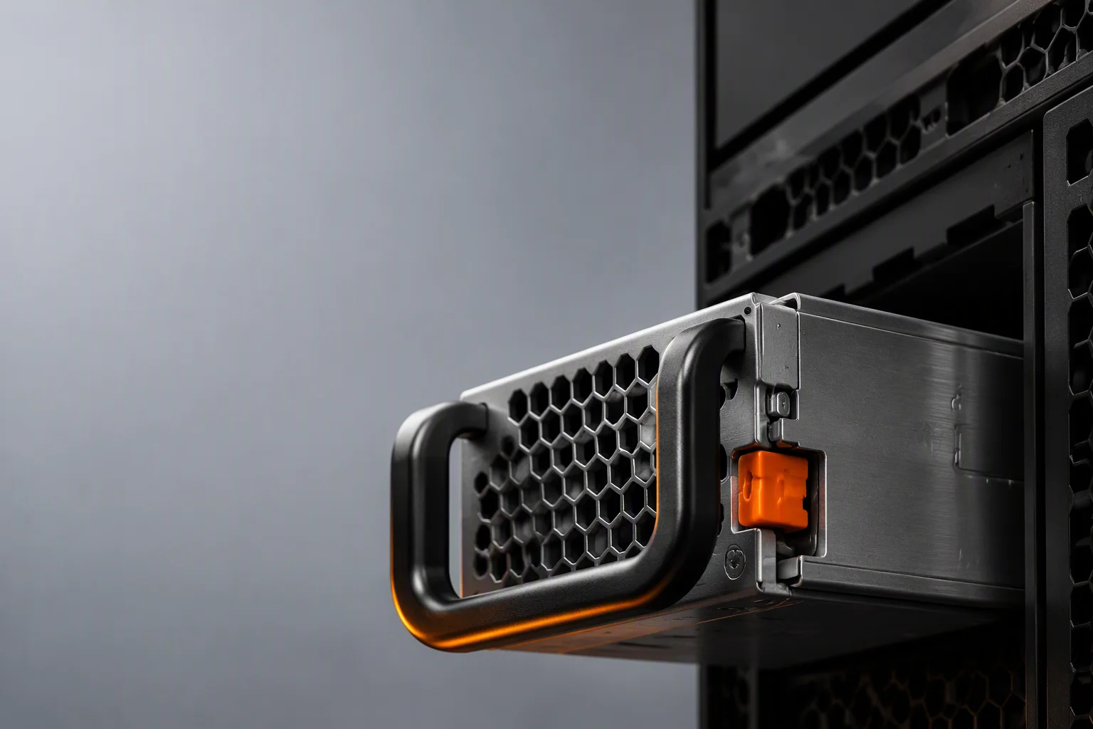
Our CRPS 550W, 800W and 1300W Titanium units are the natural fit for ToR, leaf and spine chassis: the standard 73.5×40×185mm 1U envelope, 96% peak conversion at 50% load, and — the part switch vendors actually ask about first — front-to-back and back-to-front fan options on the same electrical platform, so one PCB qualification covers every rack orientation you ship into.
Redundancy is engineered for the pull-the-module reality: hot-pluggable N+1 with active current sharing, each unit rated to carry the full switch load solo. All five protections — OVP, UVP, OCP, OTP and fan-fail — are standard, and PMBus 1.2 telemetry on smart variants feeds per-module current, temperature and fan speed to the switch CPU, so port-level monitoring and power monitoring land in the same management plane. Every batch passes ATE screening and loaded burn-in before it reaches your switch production line.
By Switch Class
| Switch Class | Recommended Part | Configuration | Status |
|---|---|---|---|
| 1RU ToR, 48×25G + uplinks | CRPS 550W / 800W | 1+1, either airflow direction | In production |
| 1RU 400G leaf / 800G ToR | CRPS 1300W | 1+1, full-load single-module rating | In production |
| Spine / high-port-count chassis | CRPS 1600W-2400W | N+1, C19 input, PMBus | In production |
Orders from 100–500 pcs; samples in 2–4 weeks, volume in 6–10 weeks including burn-in. Airflow direction is specified per order at no engineering cost.

Qualifying a New Switch Chassis?
Share your port count, power budget and rack airflow direction — we will match a wattage tier and send samples on a 2-4 week schedule.