N+N and N+1 Sizing Without Guesswork
Redundancy is usually specified as a label and sized by habit. The arithmetic that decides whether an array actually survives a failure takes about ten minutes and uses four numbers: the honest load, the module rating, the number of modules, and the ambient at the inlet.
N, N+1, N+N: What Each Configuration Actually Buys
N means the array has exactly enough modules to carry the load and no more. N+1 adds one module beyond that, so the array survives the loss of any single module. N+N splits the array into two independent groups, each capable of carrying the whole load, so it survives not only a module failure but a fault that removes an entire power path — a tripped breaker, a lost PDU feed, a failed backplane segment.
Those are different guarantees and they cost different amounts of hardware. Using an 800 W module as the unit:
| Configuration | Modules | Capacity, all healthy | Capacity after one module lost | What it survives |
|---|---|---|---|---|
| N | 1 | 800 W | 0 W | Nothing. A single point of failure by definition. |
| N+1 (1+1) | 2 | 1,600 W | 800 W | Any one module failure. |
| N+1 (2+1) | 3 | 2,400 W | 1,600 W | Any one module failure, with a spare already installed. |
| N+N (2+2) | 4 | 3,200 W | 1,600 W | A module failure or the loss of one entire feed path. |
N+N is the configuration to specify when the load itself must be considered, not just the supply. If your two PDUs land on different utility feeds, or if a single upstream breaker protects one power path, then N+1 concentrates all modules behind the same vulnerability — the extra module protects you against a supply failure but not against a distribution failure. That distinction is worth stating explicitly in the specification, because "redundant power supplies" is often read as covering both.
Sizing Arithmetic, Worked
Start from the honest requirement, not the sum of nameplates. A 2U enterprise node built from a 205 W CPU, eight 28 W DIMMs, six 12 W NVMe drives, about 40 W of board logic and two 25 W fans totals 537 W typical. Add transient and aging margin and the honest requirement lands near 650 W.
Now apply the rule that matters: the array must carry the honest requirement with the largest single module removed. Two 800 W modules in 1+1 give 1,600 W installed and 800 W on the survivor — comfortably above 650 W. In normal operation each module carries about 325 W, roughly 41% of its rating, which sits close to the load point where an 80 PLUS Titanium unit delivers its 96% peak efficiency. The same arithmetic on a 1,300 W node gives 2+1 of 800 W modules: 2,400 W installed, 1,600 W on the survivors, 433 W per module at normal load.
Scale that to a 10 kW GPU node and the choice of module rating starts to dominate the answer:
| Module rating | Array for a 10 kW node | Installed capacity | Load per module, normal | Load per module, one lost |
|---|---|---|---|---|
| 1600 W CRPS | 7+1 (8 modules) | 12,800 W | 1,250 W (78%) | 1,429 W (89%) |
| 2000 W CRPS | 5+1 (6 modules) | 12,000 W | 1,667 W (83%) | 2,000 W (100%) |
| 2400 W CRPS | 5+1 (6 modules) | 14,400 W | 1,667 W (69%) | 2,000 W (83%) |
| 3300 W M-CRPS (development samples) | 4+1 (5 modules) | 16,500 W | 2,000 W (61%) | 2,500 W (76%) |
| 5500 W M-CRPS (development samples) | 2+1 (3 modules) | 16,500 W | 3,333 W (61%) | 5,000 W (91%) |
Two lessons fall out of that table. First, small modules force long arrays: at 1,600 W you need eight modules to protect a 10 kW node, which is eight chances of a failure, eight connectors, eight fans and eight telemetry addresses. Second, running survivors at 100% of rating — the 2,000 W row — is not redundancy, it is a deferred outage. A module at 100% has no margin for a load transient, sits at the bottom of its efficiency curve, and has no headroom left for a hot inlet. Design the post-failure state to land at or below roughly 85% of rating.
How Many Units per Shelf
In an open-rack architecture the shelf, not the node, sets the module count. The ORv3 anchor is a 33 kW shelf: six 5.5 kW modules in a 5+1 array, with 18 kW shelves built from 3 kW units for smaller configurations. That is a deliberate choice of granularity, not a coincidence: six modules at 5.5 kW give 33 kW installed and 27.5 kW with one module lost, which is enough headroom that the shelf is never the constraint on how much compute a rack carries.
If you are building an internal redundant array instead, the same logic translates: pick the module count your chassis or shelf can actually hold, then choose the module rating that leaves the post-failure load at or below 85% and the normal load in the 40–70% band. Where the two constraints conflict, the module rating is the variable to move — not the count, because the count is fixed by sheet metal.
Load Sharing Is Not Optional
An N+1 array is only as good as its sharing. If two modules in parallel do not divide the load evenly, the array is effectively N with some margin on one unit and none on the other, and the weaker module ages faster because its internal temperatures are higher. Active current sharing over the digital bus holds that balance tight without the waste of droop-style sharing, which deliberately sacrifices regulation to force balance.
Sharing also gives you the diagnostic signal. Persistent imbalance — one module consistently carrying meaningfully more than its share at steady load — is the earliest indication that a sharing loop is drifting, and it appears weeks before anything trips. Expose per-module current over PMBus 1.2 and alert on the imbalance, not just on the fault.
Where the load is light, cold redundancy is worth considering: standby modules stay dark and cool while sequencing rotates which module carries the load, so fan bearings and electrolytic capacitors wear evenly across the bank instead of concentrating their hours on module one. The trade is a slightly slower response to a load step, because a dark module has to be brought up — a decision to make with your load profile in front of you, not by default.
Derating at Temperature and Altitude
Every number in the tables above assumes the module is inside its thermal rating. Two environmental factors decide whether it is.
Temperature. Our units are specified for continuous output from −5°C to +55°C ambient with a published derating curve above 45°C. Two things follow. First, read the curve rather than the endpoint: a unit rated to 55°C is not necessarily capable of full output at 55°C. Second, remember that "ambient" means the temperature at the PSU inlet, which in a loaded chassis is the room ambient plus everything the upstream components added. The last bay in a stack of hot-swap modules sees the hottest air in the node. Check the worst-case zone, not the average one.
Altitude. Air density falls with height — roughly 80% of sea-level density at 2,000 m and about 74% at 3,000 m. A fan is a volumetric device, so at 20% lower density it moves roughly 20% less air mass, and the same wattage of loss produces a higher temperature rise in the components. Altitude also affects clearance and creepage requirements in the IEC/UL 62368-1 framework, and those corrections begin above 2,000 m. Altitude derating is the single most commonly omitted line in a CRPS datasheet, so put your site elevation in the RFQ and require either a curve or an explicit statement that none applies. A supplier with no altitude answer has told you something useful.
What a Real Failure Looks Like
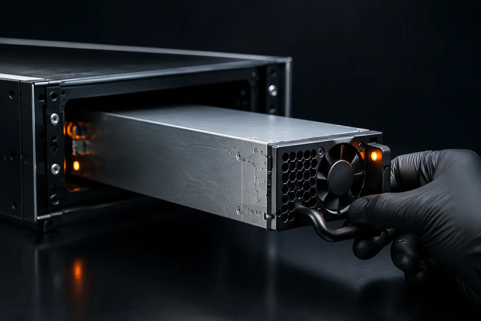
Designed right. A 5+1 array of 2,400 W modules feeds a 10 kW node. Module three's fan begins to slow. The fan-fail flag asserts, the PMBus temperature at the output NTC climbs over the following minutes, and the BMC logs a degradation event with a timestamp — still hours from any trip, because the fan register is not the only protection and OTP has not been approached. A technician extracts module three under full load; the survivors, already sharing actively, pick up the difference and settle at about 2,000 W each, 83% of rating. Output holds, the node never reboots, and the replacement rebalances into the array. The event cost one field-replaceable unit and one scheduled visit.
Sized wrong. The same node is specified at a 9 kW nameplate with five 2,000 W modules in a 4+1 array, on the assumption that 4 × 2,000 W covers it. Normal load is 9,000 / 5 = 1,800 W per module — 90% of rating, already at the top of the curve with no margin for a transient. When one module drops, the survivors must carry 2,250 W each, 112% of rating. Overcurrent protection trips the next module; the array cascades; the node goes down. Two things caused it: sizing against a nameplate instead of the honest requirement, and never computing the post-failure per-module load. Both are twenty-second checks.
Sizing Rules to Write Into the Specification
- State the honest load requirement with transients and aging margin applied — not the sum of component nameplates.
- State the configuration as N+1 or N+N explicitly, and say whether the intent is module-level or feed-path-level redundancy.
- Require the post-failure per-module load to be at or below 85% of rating at the worst-case inlet temperature on the derating curve.
- Require the normal per-module load to sit in the 40–70% band, where a Titanium unit is at or near its 96%-at-50%-load efficiency plateau.
- Require active current sharing with a stated maximum imbalance, and PMBus 1.2 per-module current reporting so imbalance is visible.
- Attach the temperature derating curve above 45°C and an altitude statement or curve for your site elevation.
- Require a live full-load extraction test as part of qualification, not a bench test at 20% load.
- Require the five protections — OVP, UVP, OCP, OTP and fan-fault — verified at ATE on every unit, with the trip points in the per-serial record.
Those are the requirements our own reliability targets are built to support: 250,000 hours MTBF at 40°C per Telcordia SR-332, continuous output from −5°C to +55°C, and hot-swap into a live backplane with N+1 and N+N topologies. If you want the post-failure arithmetic run against your own node, send the honest load figure and the worst-case inlet temperature — it is a short calculation and it is much cheaper than discovering the answer during a cascading trip.
Related Reading
PMBus on Server PSUs: a Working Guide
The registers that make array imbalance and fan degradation visible before they trip.
Read →Titanium Efficiency as a TCO Argument
How to turn efficiency points into a payback figure a finance team will accept.
Read →CRPS 1600W–2400W Titanium
High-density modules for arrays that have to survive a full-load extraction.
Explore →
Have Us Check Your Redundancy Math
Send the honest node load, the module rating and the worst-case inlet temperature — we will return the array and the post-failure numbers.
Ask an Engineer