54 V vs 12 V Rack Distribution: the Physics and the Bill
The case for 54 V is usually made with one sentence about current and one number about losses. Both are true and neither is sufficient, because the decision is really about copper mass, conversion stages, and what it costs to change a bus voltage underneath a running fleet.
The Arithmetic: Current, I²R, Copper
Conduction loss in a busbar is I²R. Raise the distribution voltage and the current needed for the same power falls in proportion; square that reduction and you have the loss reduction at equal conductor. Moving distribution from 12 V to 48 V cuts current by exactly four times and resistive line loss by roughly 16×. The 54 V bus that ORv3 standardized is that same move taken one step further, which is why the industry landed there rather than at 48 V.
At the rack level the currents involved stop being abstract. A 120 kW AI rack on a 12 V bus needs 10,000 A of distribution current. The same rack on a 48 V bus needs 2,500 A. On 54 V it needs about 2,220 A. Those numbers decide whether your busbar is a copper plate you can route and cool, or a thermal problem with a voltage on it.
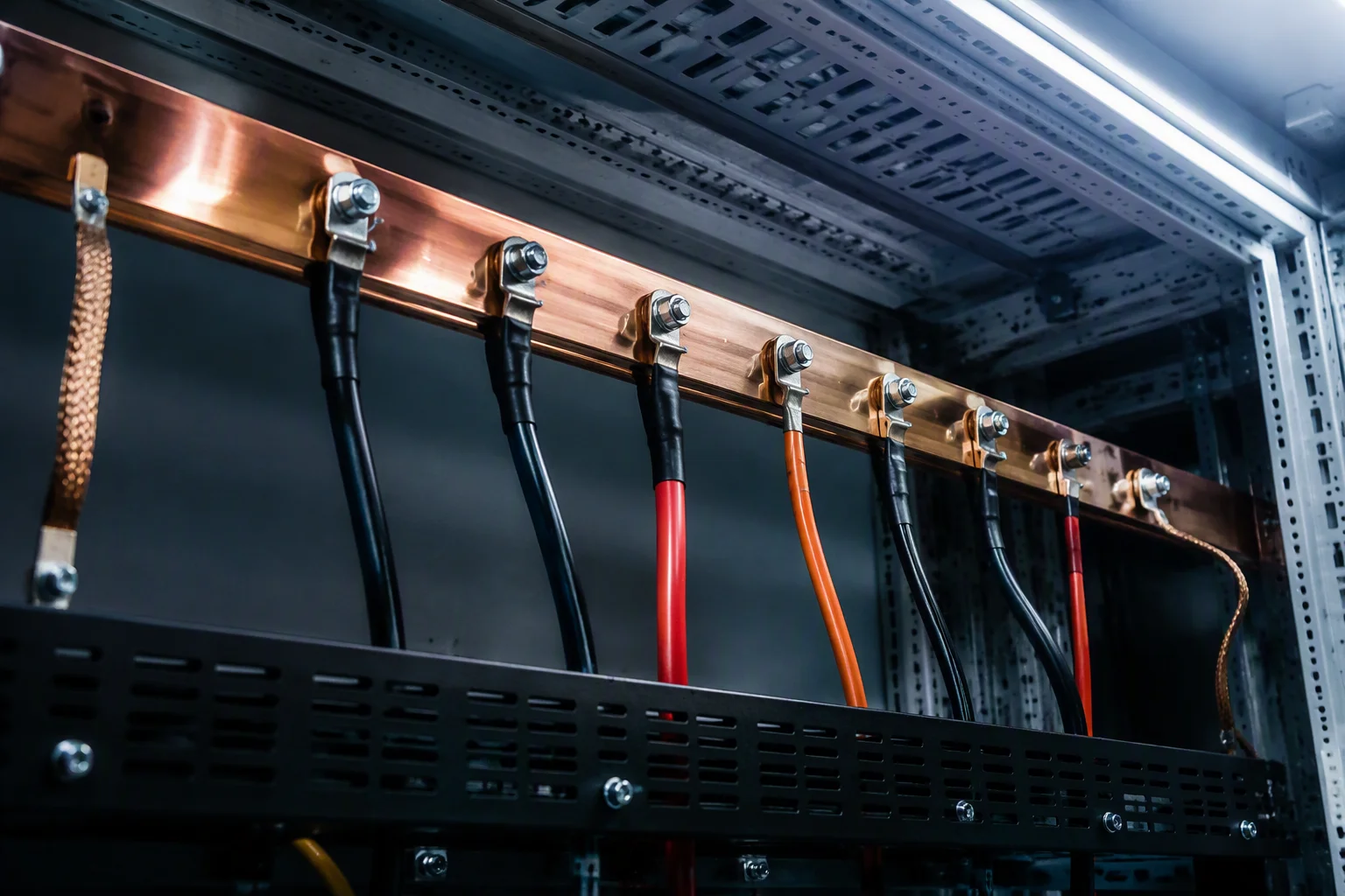
Busbar Sizing, Worked Out in Copper Mass
Abstract ratios convince nobody who has to buy copper. Take a concrete sizing target: hold busbar loss to 1% of a 120 kW rack's power — 1,200 W — over a one metre run, using copper at 1.72 × 10⁻⁸ Ω·m.
| Metric | 12 V bus | 48 V bus | Ratio |
|---|---|---|---|
| Rack power | 120 kW | 120 kW | — |
| Bus current | 10,000 A | 2,500 A | 4× lower |
| Loss budget (1%) | 1,200 W | 1,200 W | — |
| Permitted resistance, 1 m run | 12 µΩ | 192 µΩ | 16× higher |
| Copper cross-section required | ~1,430 mm² (about 143 × 10 mm) | ~90 mm² (about 30 × 3 mm) | 16× less copper |
| Copper mass per metre | ~12.8 kg | ~0.8 kg | 16× lighter |
| Loss at equal cross-section | 1,720 W | 107 W | 16× lower |
Read the table two ways, because both readings matter to different teams. If you size for a fixed loss budget, 48 V removes sixteen seventeenths of the copper — which is a procurement and mechanical-routing win before it is an energy win. If you keep the copper the same, 48 V removes sixteen seventeenths of the heat dumped into the rack spine, which is a thermal win in a cabinet that is already struggling to reject 120 kW.
Note also what the table does not say: the voltage drop is 1% in both columns, by construction. Low-voltage distribution does not fail because the drop is large in percentage terms — it fails because the current required to hit that percentage needs a conductor too heavy to install, and because every contact, joint and connector in the path adds resistance that scales with the same current.
Where the Conversion Stages Move To
Changing the bus voltage does not remove conversion loss; it relocates it. On a 12 V architecture the power supply performs one large step-down from the AC line and the board does the rest with a relatively modest ratio. On a 54 V architecture the shelf delivers 54 V to the tray, and the tray is responsible for everything below it.
That is a genuine engineering burden. Stepping 54 V to a sub-1 V core rail in a single stage is a very high conversion ratio, so most trays use two stages — 54 V to an intermediate rail, then point-of-load — or a purpose-built high-ratio converter. Each stage carries its own efficiency penalty, and the sum has to be compared against the distribution loss the higher voltage saves. On a rack with long busbar runs and tens of kilowatts per tray, the trade comfortably favours 54 V; on a short-run, low-power shelf it may not.
What does not change is the management layer. Hot-swap mechanics, protection behaviour and PMBus 1.2 telemetry remain CRPS-style at 54 V, so your rack manager sees the same register groups and the same event vocabulary. That continuity is deliberate: the bus voltage is the disruptive part of this migration, and there is no reason to make the control plane disruptive as well.
What ORv3 Standardized, and Why 54 V Won
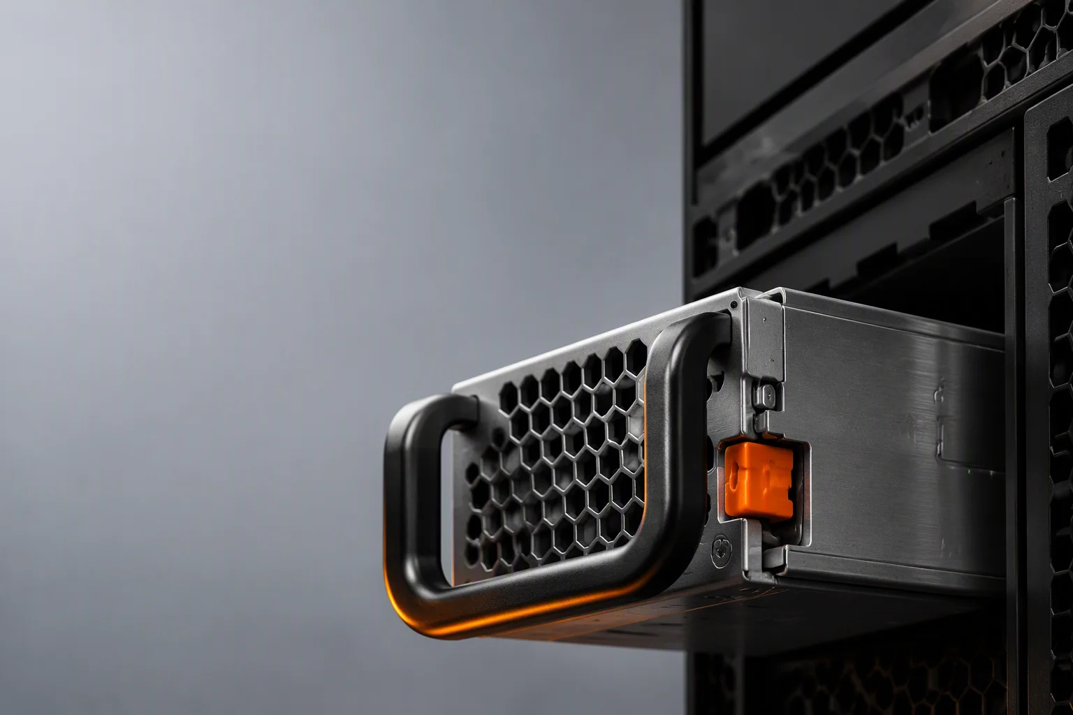
ORv3 is the open rack specification that turned the 54 V argument into an ecosystem. The anchor product is the 33 kW power shelf: six hot-plug 5.5 kW modules in a 5+1 array behind one 54 V busbar, with 18 kW shelves built from 3 kW units covering the smaller configurations. A 120 kW rack carries roughly four 33 kW shelves feeding bus segments along the spine. The shelf controller handles slot addressing, hot-plug sequencing, PMBus aggregation and throttle signalling to the hosts — which is what makes six supplies behave as one managed resource rather than six independent boxes.
The reason all of this is built at 54 V rather than 12 V is the table above, restated as a mechanical fact: at 12 V you cannot get 120 kW down a rack spine at any sensible copper mass, and the problem gets worse with every generation of accelerators, because rack power is rising while rack volume is not. ORv3 codified the answer, and the supply-side consequence is that 3 kW–5.5 kW modules with a 54 V output are now the unit of currency for open-rack power.
The Migration Cost, Itemized Honestly
Vendors who sell 54 V hardware tend to present the migration as a voltage change. It is a platform change, and the line items are these:
- Power supplies. New modules with a 54 V output section and ORv3 slot targeting. Our M-CRPS 3000 W–5500 W program is at development-samples stage with target specifications frozen jointly with each partner — this is a program slot, not a catalog order.
- Shelf or backplane. A six-slot shelf with its controller, or a reworked chassis backplane. Either way it is new tooling and a new mechanical interface.
- Busbar and hardware. New conductor, joints, standoffs and insulation. Lighter than the 12 V equivalent, but every rack has to be reworked physically.
- Tray conversion. A new converter stage on every board, with its own magnetics, layout, thermal budget and validation. This is usually the largest per-unit engineering line, and it lands on your team, not the PSU supplier's.
- Backup and hold-up. Battery backup must be 48 V-native or converted; an existing 12 V scheme does not drop in, and hold-up behaviour has to be re-verified at the new rail.
- Compliance re-work. Creepage, clearance and safety boundaries move when the distribution bus rises to a hazard-level voltage, so IEC/UL 62368-1 documentation and system-level hot-plug, EMC and backplane interoperability testing all need to be redone at the new voltage.
- Two-voltage overhead. During transition you carry spares, training and tooling for both bus architectures. Budget it explicitly rather than discovering it in year two.
Set against that: 16× less distribution copper, roughly 16× lower line loss, and a path to racks that 12 V physically cannot feed. For a new AI platform the arithmetic is not close. For an existing enterprise fleet of 1U and 2U servers drawing well under 2.5 kW per node, it is not a migration at all — it is a solution looking for a problem.
A Staged Path Off 12 V
The sensible sequence for most buyers is not a fleet-wide conversion. Keep 12 V production platforms where they are: our 550 W–2400 W titanium CRPS series is in production on the standard 73.5 × 40 × 185 mm envelope, samples in 2–4 weeks, volume in 6–10 weeks including burn-in, MOQ 100–500 units. Then run the 54 V architecture on one new rack generation, in parallel, from the tray design upward — because the tray converter is the long pole, not the power supply.
Do that pilot with the module you intend to standardize on, at the shelf level you intend to deploy, so the target specification you freeze is the one you will actually scale. Evaluation units of our 3 kW–5.5 kW M-CRPS platform are available against program slots for exactly this purpose, and the honest statement is that they are development samples, not catalog parts. If you are designing a 40 kW+ rack now, that distinction matters more than any datasheet number on this page.
Related Reading
M-CRPS for ORv3: What Actually Changed
Power classes, the 54V output section, mechanical and thermal differences, and the design implications.
Read →GPU Rack Power Trends: from 5kW to 120kW
Why the rack spine changed voltage, in three numbers per accelerator generation.
Read →Power Shelf Program
Six 5.5kW hot-plug modules, one 54V busbar, and where we stand on the shelf itself.
Explore →
Planning a 54 V Rack?
Send the rack power budget and busbar run — we will work the copper mass, the shelf count and the module rating with you.
Talk Architecture