M-CRPS for ORv3: What Actually Changed
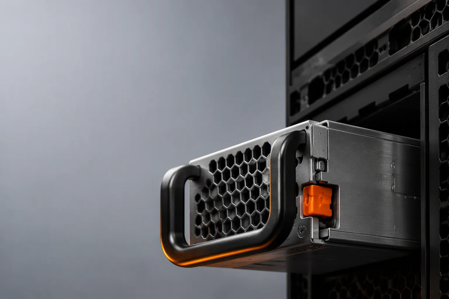
M-CRPS keeps the vocabulary of classic CRPS and changes the parts that matter: the output section, the power ceiling, the connector arrangement, and the unit of redundancy. If your rack roadmap points at 54 V, this is the format you will be specifying.
What ORv3 Changed at the System Level
Open Rack v3 approached the power problem from the rack downward rather than from the server outward. Instead of asking how much power a 1U supply could carry, ORv3 defined a shelf: a frame of hot-plug module slots sharing one output busbar, managed by a shelf controller that handles slot addressing, hot-plug sequencing, PMBus aggregation and throttle signalling to the hosts.
The numbers that came out of that framing are now the industry's reference points. The anchor shelf is 33 kW: six 5.5 kW modules in a 5+1 array behind a single 54 V busbar, with 18 kW shelves built from 3 kW modules covering smaller configurations. A 120 kW AI rack carries roughly four 33 kW shelves feeding bus segments along the spine. Once the shelf is the unit of power, the module becomes a replaceable component with a target power class and a target bus voltage — and that is exactly what M-CRPS is.
Classic CRPS Versus M-CRPS, Item by Item
The two formats share an origin and a starting envelope, which is precisely why the differences are easy to underestimate. They are architectural, not cosmetic:
| Dimension | Classic CRPS | M-CRPS |
|---|---|---|
| Spec origin | Intel specification, de facto standard | OCP open-spec evolution for ORv3 |
| Envelope | 73.5 × 40 × 185 mm (or 130 mm depth) | 73.5 × 40 × 185 mm class, split into power section and output section |
| Output voltage | Fixed 12 V main rail plus standby | 54 V primary; 12 V configuration under evaluation for mixed fleets |
| Connector | Fixed golden finger, one mechanical arrangement | Modular output section; connector tailored per platform and ORv3 slot signalling |
| Power band | 550 W–2400 W mainstream, roughly 3200 W at the industry top | 3000 W–5500 W |
| Redundancy model | Per-node N+1 or N+N inside the chassis | Shelf-level arrays, typically 5+1 with active current sharing |
| Best fit | 1U/2U servers, storage, switches | GPU nodes, ORv3 shelves, hyperscale racks |
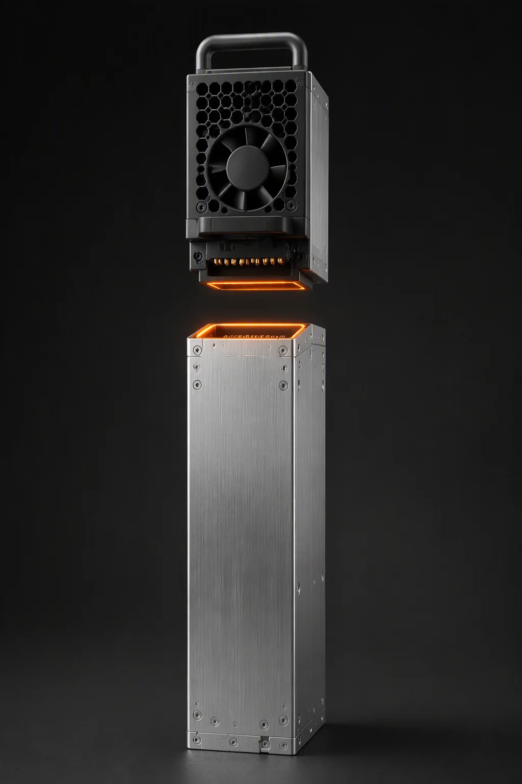
The single most consequential row is the output section. Classic CRPS fixes the power stage and the output interface together in one sealed brick: change the bus voltage and you requalify the entire supply. M-CRPS separates them, so one qualified power platform can serve a 12 V fleet today and a 54 V rack program next by swapping the output block rather than the whole unit. For a platform with a multi-year life and a rack roadmap that is still moving, that is the difference between a component and an architecture.
Power Classes and the 5.5 kW Anchor
Our M-CRPS program covers 3000 W, 3300 W and 5500 W variants under evaluation, all targeting 80 PLUS Titanium-class efficiency at 96% at 50% load on the 230 V internal redundant curve, with a 200–240 Vac single-phase input on a C20 inlet and full output available from 200 Vac.
The 5.5 kW class is the one to understand first, because it is the unit of currency the shelf arithmetic is built on. Six of them make a 33 kW shelf; 3 kW modules make an 18 kW shelf. Where the numbers stop being arbitrary is the redundancy check: 5+1 at 5.5 kW gives 27.5 kW of capacity with one module lost, which is enough that the shelf is never the constraint on how much compute a rack carries. A 3.3 kW class is the practical middle rung for nodes that sit between the classic CRPS ceiling and a full 33 kW shelf — it lets a 10 kW node run a 4+1 array with the survivors at about 76% of rating, instead of the long six- and eight-module arrays that 2 kW modules force.
Input configuration matters as much as output at these ratings. At 5.5 kW, current draw on a single-phase 230 V feed is substantial, and the C20 inlet is not a suggestion — it is the interface that makes the rating deliverable without derating. Budget your PDU, branch circuits and connector types against the shelf, not against the module.
The 54 V Output Section, and What It Moves to the Tray
Moving distribution from 12 V to 54 V cuts current by roughly a factor of four and resistive line loss by about 16×. In a rack where the busbar run between shelf and accelerator tray is measured in tens of centimetres and the rack carries 40 kW to 120 kW, that difference decides whether the spine is a copper plate you can route and cool or a thermal problem with a voltage on it. This is why ORv3 standardized on 54 V rather than 12 V, and why the power supply half of that architecture has to deliver at 54 V.
What the higher bus voltage does not do is remove conversion loss. It relocates it. On a 12 V architecture the supply performs one large step-down and the board finishes the job with a moderate ratio. On a 54 V architecture the shelf delivers 54 V to the tray and the tray is responsible for everything below — which in practice means a two-stage scheme, 54 V to an intermediate rail and then point-of-load, or a purpose-built high-ratio converter. Both carry their own efficiency penalty, and that penalty is a real line in the migration budget. Telemetry, protection behaviour and hot-swap mechanics, by contrast, stay CRPS-style at 54 V, so your BMC integration is not rewritten by the voltage change.
There is a safety dimension as well. At 54 V nominal the distribution bus sits close to the boundary where creepage, clearance and touch-safety treatment change, and the IEC/UL 62368-1 documentation for the platform has to be reworked at the new voltage rather than inherited from the 12 V design. Plan that requalification into the program, not after it.
Mechanical and Thermal Differences That Bite
Mechanically, the modular split changes what the connector has to do. A classic CRPS golden finger is one fixed arrangement carrying a 12 V rail group plus control and telemetry pins. An M-CRPS output section has to carry a 54 V rail at multi-kilowatt levels, present ORv3-compatible hot-plug signalling, and mate reliably through a blind-mate interface with a defined insertion tolerance. Slot compatibility is therefore a three-part target — mechanical, connector, and hot-plug sequencing — and it is why ORv3 slot definitions exist as a specification rather than as a drawing shared between two companies.
Thermally, the pressure rises with the wattage. A 2400 W CRPS unit in the 73.5 × 40 × 185 mm envelope already runs in the 75 W/in³ class, and the thermal design that supports it relies on a high-static-pressure 40 mm fan, an NTC-monitored hotspot map and a fan curve matched to the airflow path. A module in the 3 kW–5.5 kW range in a 1U, 40 mm-wide slot demands a materially higher watts-per-cubic-inch figure than that, with the exact number set by the slot depth frozen with the shelf. The consequences are practical: the module's airflow direction has to match the shelf, the ambient at the slot is what governs the derating curve, and the inlet in a fully populated shelf is not the room ambient.
Our target for the program is continuous output from −5°C to +55°C, with the same full protection set as the production range — OVP, UVP, OCP, OTP and fan-fault — plus PMBus 1.2 over I²C for per-section voltage, current and temperature, fan speed and event logging. Those are target specifications, and they are labelled as such on purpose.
Design Implications for Your Platform
- Redundancy moves up a level. You plan a shelf array, not a node array. A 5+1 shelf at 5.5 kW per slot is a different design conversation from two 2400 W modules in a 1U bay, and the failure analysis changes with it.
- Slot depth is frozen by the shelf. Module envelope, connector position, blind-mate tolerance and insertion force all come from the slot definition, so choosing a shelf vendor is choosing a mechanical interface for the life of the platform.
- The tray carries new work. Tray-level conversion from 54 V is your engineering, your NRE and your thermal budget. It is the longest lead item in the migration and the one most often underestimated.
- Backup strategy changes voltage. Battery backup has to be 48 V-native or converted; a 12 V hold-up scheme does not transfer, and hold-up behaviour has to be re-verified at the new rail.
- Qualification scope widens. System-level hot-plug, EMC and backplane interoperability testing become part of the module qualification, not a downstream activity.
What to Freeze Before Committing to an ORv3 Shelf
The target specification is the deliverable at the start of a program, not the datasheet at the end. Freeze these together with your module partner before tooling: slot mechanical envelope and depth; connector and blind-mate tolerance; hot-plug sequencing and inrush behaviour; output rail set and regulation window; protection trip points and ORv3-compatible signalling; the PMBus command list and how the shelf controller aggregates it; the redundancy target and permitted sharing imbalance; the inlet temperature at the slot, airflow direction, and the derating policy above 45°C; the firmware update path and record format; and the burn-in cycle and contents of the per-serial test record.
That list is deliberately long, because every item on it is cheaper to argue about on a call than to discover during an EVT build.
Where TitanWatt Stands
Stated plainly: our M-CRPS 3000 W–5500 W series is in development-samples stage, not volume production. The 3000 W, 3300 W and 5500 W variants are being built for joint evaluation with lead customers, targeting ORv3 slot compatibility at 54 V with a 12 V output configuration under evaluation for mixed fleets. Sample builds are scheduled against program slots rather than a published date, and engagement runs through four gates — spec co-creation, EVT, DVT and PVT — with the specification frozen jointly at the first gate and each subsequent gate feeding the next.
What is in production today is the classic range: titanium CRPS from 550 W to 2400 W on the 73.5 × 40 × 185 mm envelope, with samples in 2–4 weeks, volume in 6–10 weeks including burn-in, and MOQ of 100–500 units. If your rack roadmap is 54 V and two years out, evaluating an M-CRPS platform now is the right sequence — the busbar is much harder to change later than the module.
Related Reading
54 V vs 12 V Rack Distribution
The I²R arithmetic, busbar sizing in copper mass, and an honest migration budget.
Read →CRPS vs M-CRPS Explained
The side-by-side comparison and when each format is the right specification.
Read →M-CRPS 3000W–5500W (Development Samples)
The full target specification and the joint-development model behind the program.
Explore →
Co-Define a 54 V Module With Us
Send your rack architecture and power roadmap — development samples are allocated against program slots.
Join the Early-Partner Program