The CRPS Mechanical Envelope, Dimension by Dimension
The datasheet line reads 73.5 × 40 × 185 mm, and most buyers stop reading there. Each of those three numbers closes a door somewhere else in the chassis. Here is what every dimension actually constrains, and where chassis designs get into trouble.

Three Numbers, Three Constraints
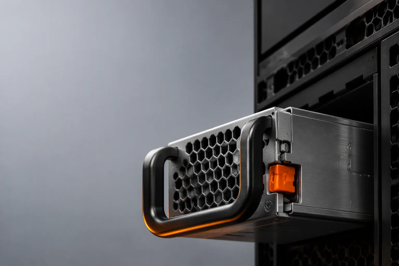
The CRPS-185 module is a 1U, 40 mm-wide, 185 mm-deep brick with a fixed golden-finger connector at the rear. Because the envelope and connector are shared across vendors, a qualified unit drops into any CRPS chassis — and because they are shared, every dimensional decision you make in the chassis is made against someone else's drawing.
| Dimension | Value | What it constrains |
|---|---|---|
| Width | 73.5 mm | Bay pitch and cage width. A 19-inch rack's 482.6 mm of usable frontage takes six 73.5 mm bays with clearance left over. |
| Height | 40 mm | Sets the 1U module height and caps fan diameter at 40 mm. It also fixes the blanking and latch geometry runners are tooled around. |
| Depth | 185 mm | Backplane position, the cable-routing zone behind the power bay, and how much of the chassis the power section eats. A 130 mm-deep CRPS-130 variant exists for compact chassis. |
| Mass | Roughly 1.2 kg finished | Rail loading on the sled, latch and retention design, and shipping packaging. Two units in a 1U bay is a handling decision as much as an electrical one. |
| Volume | About 33 in³ | Power density. A 2400W unit in this envelope runs in the 75 W/in³ class — that number, not the wattage, is what the thermal design has to survive. |
The width figure deserves a second look. Six bays of frontage sounds generous until you remember that the same frontage has to hold drive carriers, PCIe brackets and airflow grilles. In practice a 1U server takes two CRPS bays, a 2U takes two to four, and a storage enclosure may fan out across a full row — which is why the power bay is usually the first thing frozen in a chassis layout, not the last.
The Sled and Cage: Where Tolerance Actually Lives
A CRPS module is not installed so much as guided. The cage rails take the unit, the latch retains it, the handle provides the extraction force, and the golden finger has to land on the backplane with enough alignment left over to survive a few thousand hot-swap cycles. That is a tolerance stack with five contributors, and it is the reason "CRPS-compatible" is a weaker statement than it sounds.
Three checks catch most of the problems before they reach a line. First, confirm the latch direction and handle clearance against your cage — a latch that needs 15 mm of finger space behind a cable tray is a serviceability defect that only appears in the field. Second, confirm the extraction path: the module has to leave the bay without removing anything else. Third, confirm the backplane connector tolerance against the drawing your chassis vendor actually tooled to, not the one in the specification.
We validate every production lot against the mechanical dimensions and connector tolerance of the 73.5 × 40 × 185 mm envelope, and line-side inspection confirms golden-finger geometry and fit before a unit is packed. Process engineers own those tolerances because they are what decide whether a power supply drops into your chassis or becomes a rework ticket. A first-article fit-check checklist travels with every sample kit so your integration team can run the same test on your bench.
The Golden-Finger Connector and What the Pinout Carries
The rear connector is the most standardized part of the whole format, and also the place where a mismatch does the most damage. The pins that matter to your integration are the 12V rail grouping (how many contacts carry the main rail, which determines per-contact current and hot-plug arcing behavior), the +5VSB standby feed, PS-ON and PS-KILL control, POK/PWR-OK status, and the I²C/PMBus pins on smart variants.
The classic silent failure in this list is POK polarity. A unit wired to the wrong POK polarity boots happily on the bench and blocks POST in the rack, and because nothing has failed electrically, the fault gets attributed to the motherboard for a week. Verify PS-ON, PS-KILL and POK/PWR-OK polarity against your own schematic before the first article goes into a production chassis, not after.
Standby current and PS-KILL timing are the other two lines worth reading closely. PS-KILL is what lets a shelf controller or BMC cut a module out of the array on command; if your timing expectation and the unit's response window disagree, hot-swap sequencing across a multi-module bank will behave inconsistently under load even though every individual unit passes test.
Airflow Direction Is a Chassis Decision, Not a PSU Decision
CRPS units are available with front-to-back or back-to-front airflow, and the choice belongs to the rack's thermal plan. Fitting a counter-flow supply into a chassis that pushes air the other way recirculates exhaust through the power bay — a common and thoroughly misdiagnosed cause of thermal throttling in mixed-vendor racks, because the symptom shows up at the CPU while the cause sits at the back of the chassis.
The airflow path inside the 40 mm envelope is built around a 40 mm high-static-pressure fan, or a twin 40 mm array on higher-wattage members of the family, with an NTC-monitored hotspot map driving the RPM curve. That design works only if intake is not choked. Keep the service-clearance zone in front of the fan face free of cables and blanking-panel leakage, and keep inlet meshes serviced; a partially blocked power bay on a 2400 W unit is a derating event waiting for a hot afternoon.
Remember also that the ambient your power supply sees is not the room ambient. It is the room ambient plus everything upstream in the airflow path — CPUs, DIMMs, drives, NICs. In a dense node the last bay in a stack of hot-swap modules sees the hottest air in the chassis. Our units are rated for continuous output from −5°C to +55°C ambient with a published derating curve above 45°C, which is generous, but it is measured at the PSU inlet. Design the bay, then check the number.
What the Envelope Does to Your Power Ceiling
Vendors have climbed the same envelope patiently: 550 W, 800 W, 1300 W, 1600 W, 2000 W, 2400 W, with specialist designs reaching roughly 3200 W at the top of the industry range. Every step came from topology and materials rather than from space — LLC resonant conversion, synchronous rectification, denser magnetics, better heatsinking. None of it creates volume.
Past roughly 2.5 kW the fixed envelope starts fighting physics. Magnetics and heatsinking want space the format does not have, a single 40 mm fan approaches its acoustic and pressure limits, and the input side becomes a constraint of its own: a 2400 W rating requires a C19/C20 inlet and full rated output from 200 Vac, because a 120 Vac / 15 A C13 feed simply cannot carry the input current.
That is the practical ceiling of classic CRPS, and it is why the format is not the answer for a 10 kW node. There, the arithmetic pushes you toward either more bays running an N+1 array of 1600 W–2400 W units, or the modular M-CRPS path at 3000 W–5500 W with a 54 V output section and ORv3 slot targeting. Both are legitimate; the deciding question is whether your chassis has frontage left and whether your roadmap is heading for a 54 V rack.
Specifying the Envelope on the Purchase Order
Vague mechanical language is where first-article builds slip. Put these lines in the specification instead:
- Envelope: CRPS-185, 73.5 × 40 × 185 mm, 1U hot-plug, or the CRPS-130 depth variant if the chassis requires it.
- Airflow direction: front-to-back or back-to-front, stated per bay position rather than per chassis if the rack has mixed zones.
- Connector: golden-finger pinout with 12 V rail grouping, +5 VSB standby, PS-ON, PS-KILL, POK/PWR-OK polarity and I²C/PMBus pins defined against your schematic revision.
- Retention and serviceability: latch direction, handle clearance, and an extraction path that does not require removing other FRUs.
- Rating and environment: continuous output from −5°C to +55°C ambient with the derating curve above 45°C attached, and the inlet type stated (C14 below the 1600 W class, C20 for the 1600 W–2400 W units at full output).
- Evidence: per-serial ATE test record covering efficiency at 10/50/100% load against the 90/96/91% Titanium gate points, protection trip points, and PMBus register readback, plus the burn-in batch record.
Our 550 W, 800 W and 1300 W units are in volume production on this envelope today, with the 1600 W–2400 W series covering the high-density end, samples in 2–4 weeks and volume in 6–10 weeks including burn-in. If the mechanical envelope is what you need help with first, send the chassis cutout drawing and the cage outline — that conversation is cheaper before tooling than after.
Related Reading
CRPS vs M-CRPS Explained
The fixed envelope versus the modular 54V format — where classic CRPS ends and M-CRPS takes over.
Read →PMBus on Server PSUs: a Working Guide
The registers worth polling, threshold discipline, and how to wire PSU telemetry into rack management.
Read →CRPS 1600W–2400W Titanium
75 W/in³ class modules inside the same 1U envelope, in production today.
Explore →
Send Us the Chassis Drawing
Cutout, cage outline and airflow direction — we will confirm envelope fit and connector tolerance before you tool anything.
Talk to an Engineer